Quick Links: Introduction – Initial Planning – Disassembly – Assembly – General Firmware – Stepper Calculations – BLTouch – PID Tuning – Stock LCD – Files – Final Notes
Introduction
This is the placeholder for my Wanhao i3 (aka Monoprice Maker Select V2) conversion to a 32 bit board with 2209 drivers using the SKR 1.4 non turbo board. I attempted a Marlin 1.1.x load with BLTouch on my i3 and the BLTouch never would work. I removed the C7 capacitor just like the BLTouch instructions said; however, I tried to home the machine (G28 code) after removing the capacitor and the nozzle would crash into the bed and keep driving down. I manually tested the Z-Endstop with my multimeter at the switch and at the circuit board connector and it did indeed work and provide continuity. Removing the C7 must have damaged something on the board, so without a way to stop the nozzle from breaking the bed I’ve resorted to upgrading the mainboard on this machine. Initially I followed Chasetec’s instructions to simply upgrade my Melzi board to include BLTouch. He has some great info there if you’re on a stock machine and want to explore better firmware like Marlin. Now I’m reading an outdated guide on upgrading to an SKR 1.4 board. My hope is to document my build log here and provide an updated working guide for others trying to go from Melzi on their i3 to a SKR 1.4.
Initial Planning
I watched Chris Warkocki’s video on how he setup his 1.4 on his Prusa machine. It helped on some items but since we have different machines I had to source my information from several other sources as well. I mentioned above I used this guide as well, and I sourced many other tidbits from Reddit, Thingiverse, and Facebook (Multiple groups).
I wasn’t sure which motor “driver” to go with either when I started researching all of this. The most common two are 2208 and 2209 drivers. 2209’s provide sensorless homing and seemed more future proof to me. They also handled slightly more voltage and run cooler so I went with them. I also didn’t understand why people were all geeked out about UART drivers vs SPI etc. Just buy UART because anything you want to change about them can be done via code instead of soldering on jumpers or setting other things via hardware. UART makes it all so much simpler.
Disassembling the Melzi board
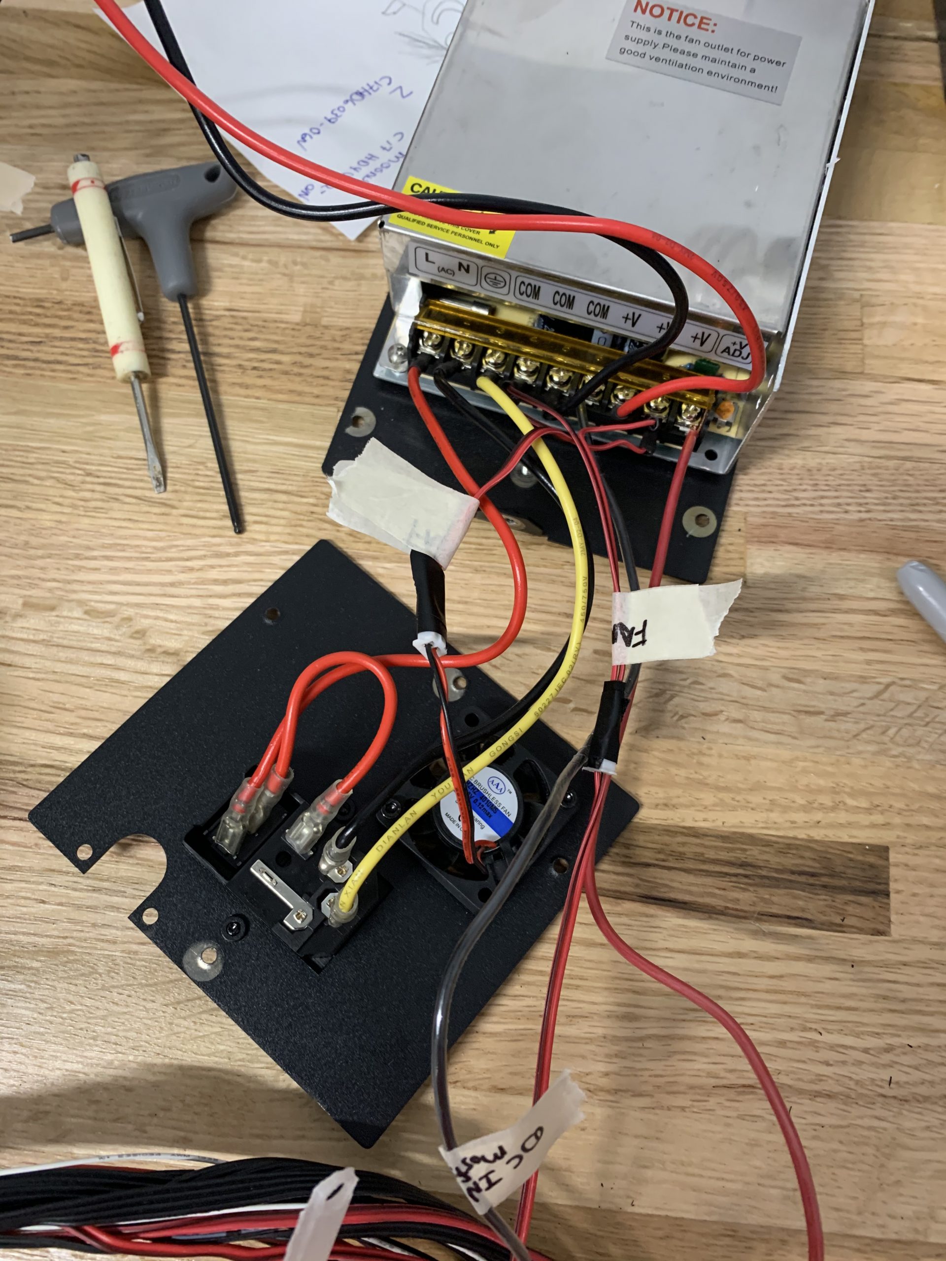
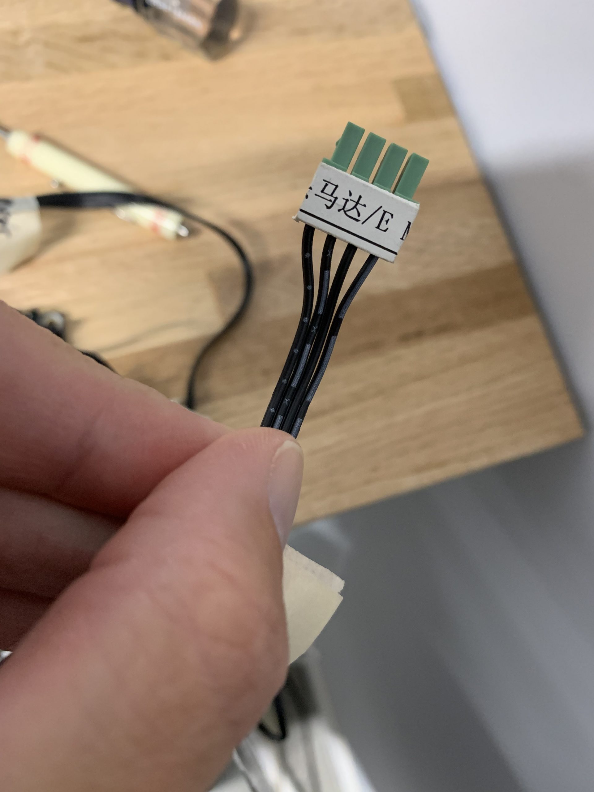
When I started taking things apart I first had to unwrap all the cables from that plastic loop guard that came on my kit. Then I used a 2.5mm allen key to take the control box apart. Then get some masking tape and MARK EVERYTHING. I even took a few pictures to help remember which way things went. I labeled X, Y, Z stops, all motor connectors, thermosistors, hot bed, etc. It looks like a mess of masking tape. Pay special attention to the extruder wires. I recommend labeling them before you remove the connector by looking at the underside of the Melzi board.


Assembling the SKR 1.4
Now starts the fun part, putting it all back together. Most of the assembly was pretty straight forward. Here is a diagram that will help clear up some contact points.

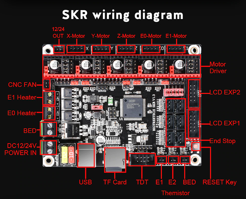
Pay special attention to several connectors in particular where the alignment of positive and negative are OPPOSITE of the connector next to it. FAN Connectors, BED, Power In, E0 (Extruder power) etc. Please refer to both of the diagrams above to ensure you are doing it right. Double and triple check so you don’t get magic smoke when you power it on. Here is a picture of mine completely hooked up. I did not apply power to it in this situation and sorry for the mess.


If you look close at the board there you’ll see I use a mossfit bed heater and extended the control wire. I also added some extensions to the BLTouch. You’ll notice some of the connectors do NOT plug into the control without some modification. Here is how you get them to fit in. Make sure you plug the end stops into the correct 2 pins and don’t use the 5v pin. Refer to this video below or look at the schematic above.
Firmware and Code
The firmware took SEVERAL iterations to get working even slightly correctly. The biggest issue I had was that I didn’t want to cut the diagnostic pins on the 2209 drivers. I don’t think I have room to bend them like the 1.3 revision of the board was able to do. This means I’ll have to play with sensorless homing. **Update** I actually gave up on sensorless homing. It has too many sensitivity problems in my experience. I could never get the thing to home right so I disabled it completely. This means I did 3 main things. I inverted the end stop logic on the X and Y, Bent the diagnostic pins on my 2209’s for X & Y toward the motor wire connectors (Z0 etc), and removed the code for sensorless homing.
Note about Z drivers. You will be using 1 2209 to drive both Z motors. Plug your Z cables into Z0 and Z1 and make sure in configuration_adv.h you set the Num_Z_Drivers to 1.
There has been a LOT of confusion on the type of thermisistor to use in the configuration.h file. It seems the Wanhao i3 (MMS) shipped with numerous configurations. Most people either used the default “1” or “13” even though it clearly states in the code that most Monoprice Maker Selects should choose “11”. A user pointed out this bug report that outlines a more precise way of setting your correct thermisistor. In my specific case I initially chose wrong and picked “13” because that’s what most of the guides used. Please look at the link above. I will eventually change my setting to:
#define TEMP_SENSOR_0 99 //because I have R4 and R5 from my Melzi board labeled 1002.Stepper Drivers
I’m struggling with a few final items before I start assembling my final code. I researched the stock stepper drivers so I could calculate the correct mA rating for the firmware settings in Configuration_adv.h. It appears I have Moon CH17HD40102-01N and -06N etc. A smart person before me decoded it and here’s their info.
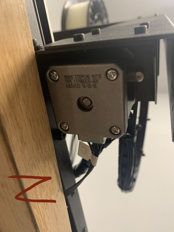


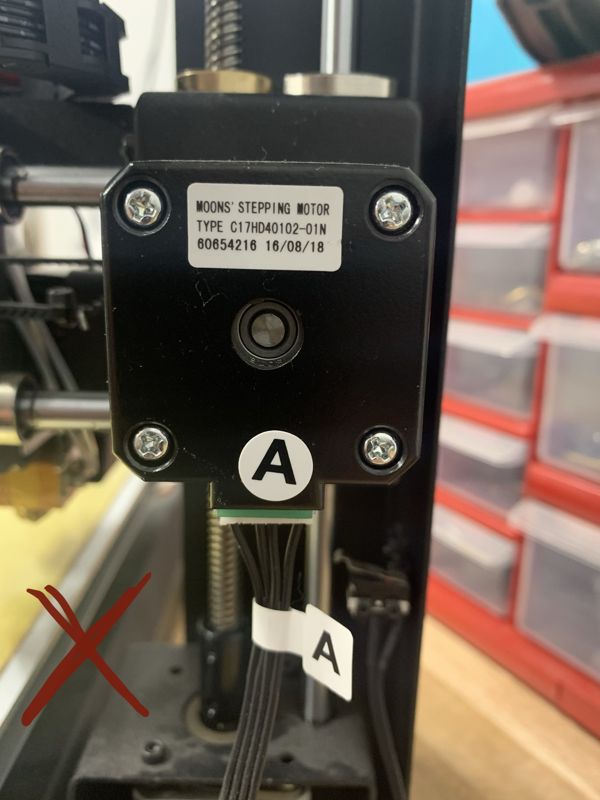

Each stepper is basically 1.02 amps max. Marlin says use max amps divided by 1.414 to come up with the correct milliamp rating. I calculated 730 for my steppers; however, a guide I’ve been referencing says to use 760. I’m going to monitor my temps and try 734 initially. Here’s the math:
1.02 x 8 x .1 = .816
.816 x .9 = .7344
I’ve heard from others that there is a Facebook group where some of the people have used higher voltages with better results. I’ll look into that later.
Sensorless Homing
I never could get sensorless homing working correctly. I spent a LOT of time tweaking without consistency. One thing I did NOT try was to lower the homing voltage by half then try sensorless homing. If you change #define X_CURRENT_HOME X_CURRENT in the configuration_adv.h to something like (X_CURRENT / 2) I’ve heard reports of much better homing. Others have reported changing the speed of the homing has helped. Here are two web pages that discuss what helped them if you want to try – one and two.
BLTOUCH is working – credit to Marcelo on the BTT Github
Step 1 (and probably the most important one!!!): CHECK YOUR BL TOUCH V3.1 CABLE!!
Quote from Marcelo: I’m using a BL Touch (Classic) in my RepRap, and when I bought my Ender 3 Pro I also bought the Creality BL Touch Kit (bought mine on Amazon, but is the original Creality kit – https://www.amazon.com/gp/product/B07SCLF42D/). During installation on the original board, I observed on the Creality installation guide (Guide) that the long cable that come in the kit had a difference on pin-out while compared with my original BL Touch. If you look on the guide linked above, frame 5, you will see that Servo (3 pin) pin-out on the pinboard A (the adapter that comes in the kit to connect the BL Touch together with LCD display in the original Creality board (the one that came on my Ender 3 Pro was Creality3D V1.1.4) has the following sequence:
SIG
GND
VCC
But if you look into SKR1.4 manual (SKR 1.4 manual), page 8, you will see that the sequence of pins on the Servo connector is:
GND
NPWR (VCC)
2.0 (SIG)
which is different from the cable that come in the Creality BL Touch Kit (in Creality kit the GND is in the middle, in SKR 1.4 (or 1.4 Turbo) VCC is in the middle.
So if you are using an Creality BL Touch kit and switching to SKR 1.4 (or 1.4 Turbo) please verify your wiring to match BTT SKR 1.4 board. In my case I had to exchange the position of VCC and GND pins in the cable connector (the 3 pin connector). This can be done using and X-Acto knife (or similar), raising the retainer, pulling out gently the wire with the metallic connector, and inserting it on the correct position (in my case I had to invert blue and red wires, but please check your cable properly!!!).
IMPORTANT: if you bought a BL Touch from other vendor please check the cabling. I had an original BL Touch bought from Antclabs that the wires already match the BTT SKR 1.4. SO PLEASE BE CAREFUL!!!
Step 2: Connect the BL Touch V3.1 to the SKR 1.4 (or 1.4 Turbo) using the original BL Touch connectors on the board
Look into SKR1.4 manual (SKR 1.4 manual), page 8, and connect your BL touch as showed there. The 3 pin connector is connected on the Servo connector, and the 2 pin connector is connected to the Probe connector.
Step 3: Upgrade your firmware
I started by upgrade using a vanilla version of Marlin bugfix-2.0.x (https://github.com/MarlinFirmware/Marlin/tree/bugfix-2.0.x), and used the config examples from Marlin Configuration (https://github.com/MarlinFirmware/Configurations/tree/bugfix-2.0.x). To do that, you copy the files from the folder config/examples/Creality/Ender-3 that you downloaded from Configurations to the Marlin folder from the bug fix-2.0.x version.
IMPORTANT CHANGES ON CONFIGURATION FILES:
Configuration.h
#define MOTHERBOARD BOARD_BTT_SKR_V1_4 or #define MOTHERBOARD BOARD_BTT_SKR_V1_4_TURBO (adjust to your motherboard)
#define X_DRIVER_TYPE TMC2209 (uncomment and adjust to YOUR DRIVER TYPE) <== Only TMC2209 or TMC5160
#define Y_DRIVER_TYPE TMC2209 (uncomment and adjust to YOUR DRIVER TYPE)
#define Z_DRIVER_TYPE TMC2209 (uncomment and adjust to YOUR DRIVER TYPE)
#define E0_DRIVER_TYPE TMC2209 (uncomment and adjust to YOUR DRIVER TYPE)
//#define Z_MIN_PROBE_USES_Z_MIN_ENDSTOP_PIN (COMMENT IT, otherwise Marlin will try to use Z_MIN_ENDSTOP_PIN for probing)
#define USE_PROBE_FOR_Z_HOMING (uncomment it, to enable homing using BL Touch)
#define Z_MIN_PROBE_PIN P0_10 (uncomment it, and change to SKR 1.4 probe pin - P0_10)
#define BLTOUCH (uncomment it)
#define AUTO_BED_LEVELING_BILINEAR (uncomment it, to allow auto bed leveling using the BL Touch) – NOTE: I used UBL leveling in my code. At the current time 5/14/20 Marlin bugfix 2.0.x leveling is totally messed up according to their discord. I had to do a G29 P1 to build a mesh and then G500 to save the mesh. It only measured 50/100 spots in my case and I’m not sure why. This is another area I’ll have to keep up on. It MAY be fixed on the 5/13/20 version.
#define Z_SAFE_HOMING (uncomment it, it ensure proper X and Y homing before Z homing, avoiding probing outside the bed area, and nozzle crashing the bed)
Configuration_adv.h
#define SENSORLESS_BACKOFF_MM { 2, 2 } (uncomment, and define the backoff before sensorless homing - important if X or Y are already at 0)
#define HOMING_BUMP_MM { 0, 0, 2 } (change first 2 numbers to 0, to avoid duplicate bumping - crashing! - to your structure)
//#define QUICK_HOME (comment, since simultaneous X and Y homing in diagonal is still not working 100%, this will home first X, than Y)
#define MONITOR_DRIVER_STATUS (uncomment, allow better information about trinamic drivers like TMC2209 via G-Codes M906, M911, M912, M122)
#define SENSORLESS_HOMING (uncomment, allow sensor-less homing)
#define X_STALL_SENSITIVITY 8 (uncomment, and adjust your sensitivity - mine is 50)
#define Y_STALL_SENSITIVITY 8 (uncomment, and adjust your sensitivity - mine is 50)
//#define Z_STALL_SENSITIVITY 8 (comment, to NOT use sensorless homing in axis Z - you will use BL Touch!!)
NOTE: I’m not sure what driver the author of this section was using; however, I was using 2209s. When I had everything almost working my sensitivities were much different than his. Mine were Y_STALL_SENSITIVITY 120 and X_STALL_SENSITIVITY 118. I have been on the Wanhao Facebook group and have had several other responses: Kasey said “X homing sensitivity: 25 Y homing sensitivity: 60” and AAron said “X homing sensitivity: 80 Y homing sensitivity: 78“. All of this tells me it’s all over the place and it really has to work for your application.
#define TMC_DEBUG (uncomment it, necessary together with MONITOR_DRIVER_STATUS)
Step 4: Compile and install new firmware, and test it!
Compile and install your new firmware, and install it. Test it properly, and after it perform normal initial setup of your printer (Z Offset adjustment, bed leveling, etc.).
Again, my hardware configuration:
- Creality Ender 3 Pro
- BTT SKR 1.4 Turbo
- TMC2209 drivers
- BTT TFT35 V3.0 E3
- Creality BL Touch Kit (BL Touch connected to Servo and Probe pins, NOT to Z-Stop pins)
With that configuration, I was able to achieve (properly tested):
- Sensorless homing on X and Y axes;
- BL Touch homing on X axis;
- Auto Bed Leveling using BL Touch;
PID Tuning Before You Print
After we finally get everything back together we need to do a PID tune. This adjusts the electronics to be more accurate for print temperatures and will be different for every machine. You will need to do this for yours and only consider my numbers as an example. I’m using Octaprint but you can use Arduino serial viewer or Pronterface etc to view terminal window info.
Start with a cold hot end and bed so it’s as close to room temperature as possible. I have a spool of ABS sitting here and I print that at around 240C before the conversion, so now I’ll send the following command to start the auto PID tuning: “M303 S240”. We will let the machine ramp up the temperatures as we watch the progress window for the cycles to complete. Once complete it will print out our K values for our firmware. Overwrite your values in the configuration.h and save it. You should now use your menus to replace the PID values for the nozzle via the LCD or you can use gcode like this:
M301 P23.82 I1.61 D87.93 //my printer settings.
M500 //to save to EEPROM
This takes care of the nozzle PID. I am unsure if it did the bed so I ran that code separately as well after a full cooldown. Use this gcode for the bed:
M303 E-1 S60 C8
M304 P1 I2 D3 //Write the bed settings
M500 //to save to EEPROM
Once that’s complete write those values down and enter them back into the firmware too.
Here is a video describing the process for those who like to watch videos.
Getting the Stock LCD Working
You can get the stock LCD screen working courtesy of Henrik:
For those who struggles to connect the stock wanhao i3 1.2 LCD display. I got it working by connecting the following pins:
pin 1 LCD CS –> 1.19 EXP 1
pin 2 Encoder B –> 3.25 EXP 2
pin 3 LCD Data –> 1.18 EXP 1
Pin 4 Encoder A–> 3.26 EXP 2
pin 5 LCD SCLK –> 1.20 EXP 1
pin 6 Encoder Button –> 0.28 EXP 1
pin 7 ESTOP –> I dont use that one- so did not try to find it
pin 8 Beeper –> 1.30 EXP 1
Pin 9 5v –> 5V EXP 1
pin 10 GND –> GND EXP 1
LCD pins should like this:
1 2
3 4
5 6
7 8
9 10
Files
Here is a collection of Cura Profiles and links to other files that have helped me along the way. Credit is due to their respective authors.
- Cura Profiles
- Firmware @ my GitHub
Final Notes
This final section is going to be a collection of notes that helped me along the way and some thoughts on the future of this build / conversion.
- The Facebook group for such an old printer is amazingly busy. I don’t get on Facebook much these days but I can’t ever leave because of resources like this. I highly recommend this group over reddit or other sites for our printers.